Troubleshooting

|
WARNING: Fire, Explosion, or Electrical Shock Hazard. Can cause severe injury, death or property damage. Do not attempt to modify the physical or electrical characteristics of this device in any way. Replace it if troubleshooting indicates a malfunction. |
Important:
-
The following service procedures are provided as a general guide. Follow appliance manufacturer’s service instructions if available.
-
Meter readings between the gas control and ignition control must be taken within the trial for ignition period. Once the ignition control shuts off, lockout models must be reset by setting the thermostat down for at least 1 minute before continuing. On retry models, wait for retry or reset at the thermostat.
-
If any component does not function properly, make sure it is correctly installed and wired before replacing it.
-
The ignition module cannot be repaired. If it malfunctions, it must be replaced.
-
Only trained, experienced service technicians should service direct ignition systems.
-
After troubleshooting, check out the system again to be sure it is operating normally.
Preliminary Checks
Note: Before troubleshooting the system, perform the following checks:
-
Verify power to the heating appliance and the S8901. Voltage to the S8901 should be between 20.5 and 28.5 Vac.
-
Ensure that that the manual shutoff valve in the supply line and the gas cock knob on the combination gas control valve are open.
-
Check all wiring connections to ensure that they are clean and secure.
-
Make certain the S8901 is not in safety lockout.
-
De-energize the system by lowering the thermostat set point below room temperature.
-
Wait at least 1 minute, then re-energize the system by raising the thermostat set point 5°F above room temperature.
-
-
Inspect the ceramic insulator on the flame sensor
-
Check the flame sensor and its mounting bracket. Correct the position if bent out of shape.
-
Review the S8901 normal sequence of operation.
General troubleshooting process as it follows:
-
Refer to LED Status and Troubleshooting for LED status codes.
-
Perform the Checkout as the first step in troubleshooting.
-
Check the troubleshooting guide (See Troubleshooting Guide) to pinpoint the cause of the problem.
-
If troubleshooting indicates an ignition problem, see Ignition System Checks below to isolate and correct the problem.
-
Following troubleshooting, perform the Checkout again to be sure system is operating normally.
Ignition System Checks
Step 1: Check Igniter Wiring Harness
Make sure:
-
Ignition wire does not run in contact with any metal surfaces.
-
Connections to the ignition module and to the igniter or igniter-sensor are clean and tight.
-
Ignition wire provides good electrical continuity.
Step 2: Check ignition system grounding. Nuisance shutdowns are often caused by a poor or erratic ground.
A common ground is required for the module and the burner bracket.
-
Check for good metal-to-metal contact between the igniter bracket and the main burner.
-
Check the ground circuit from the GND (BURNER) terminal on the module to the main burner. Make sure connections are clean and tight. If the wire is damaged or deteriorated, replace it with 14- to 18-gauge, moisture-resistant, thermoplastic insulated wire with 221°F (105°C) minimum rating.
-
If the flame sensor or bracket is bent out of position, restore it to the correct position.
-
Check temperature at the igniter ceramic or flame sensor insulator. Excessive temperature will permit leakage to ground. Provide shield if temperature exceeds rating of igniter or sensor.
-
Replace igniter and sensor or igniter-sensor with identical unit if insulator is cracked.
Step 3: Check flame sensing circuit.
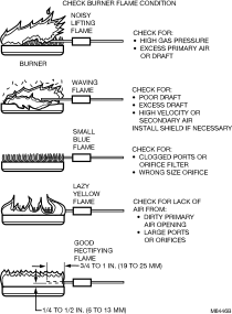
Make sure burner flame is capable of providing a good rectification signal. Check conditions as shown in Check Burning Flame Condition.
-
Make sure about 3/4 to 1 in. of the flame sensor or igniter sensor is continuously immersed in the flame for best flame signal. See burner flame condition figure. Bend the bracket or flame sensor, or relocate the sensor as necessary. Do not relocate an igniter or combination igniter-sensor.
-
Check for excessive (over 1000 °F [538 °C]) temperature at ceramic insulator on flame sensor. Excessive temperature can cause short to ground; move sensor to cooler location or shield insulator. Do not relocate an igniter or combination igniter-sensor.
-
Check for cracked igniter-sensor or sensor ceramic insulator, which can cause short to ground, and replace unit if necessary.
-
Make sure electrical connections are clean and tight. Replace damaged wire with moisture-resistant No. 18 wire rated for continuous duty up to 105 °C [221 °F].
-
-
If the igniter is other than a Norton 201 or 271, make sure it meets the following specifications.
-
Igniter must reach 1000 °C [1832 °F] within 36 seconds with 102 Vac applied.
-
Igniter must maintain at least 500 M ohms insulation resistance between the igniter leadwires and the igniter mounting bracket.
-
Igniter must not develop an insulating layer on its surface (over time) which would prevent flame sensing.
-
Igniter surface area immersed in flame must not exceed 1/4 of the grounded area immersed in flame. This would prevent flame sensing.
-
Igniter current draw at 132 Vac must not exceed 5 A.
-
Step 4: Check main burner lightoff.
-
Set the thermostat to “Call for Heat" and observe the main burner during the ignition sequence.
-
Make sure the igniter warms up and glows red. If not, check for 120Vac across L1 and L2 and that L1 and L2 are not reversed.
-
Check that the main burner lights. If not check the following:
-
Check that Main Gas is flowing. Check all main gas supply valves are open, supply tubing is good, pressures are good, and main burner orifice
-
Check Electrical connections between the module and Gas Valve.
-
Check for 24Vac across MV Terminals on the Module. If Voltage is okay, replace the gas valve. If not, replace the module.
-
-
Note: If Control goes into Lockout or retry delay, reset the "Call for Heat".
-
Does the main burner remain powered and lit? if not, check the following:
-
Check continuity of ground wire.
-
Make sure L1 and L2 are not reversed, This would prevent flame detection.
-
Check that the main burner flame covers the igniter/sensor or sensor. Adjust the main burner Flame if necessary.
-
If Problem persists, replace the module
-
LED Status and Troubleshooting
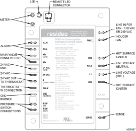
This control has one LED used for flame sensing and system status:
Location of LED
|
LED Flash Code |
Indicates |
Description |
Next System Action |
Service Action |
|---|---|---|---|---|
|
3 fast blinks |
Test / |
Calibration on power up. |
No action needed. |
No action needed. |
|
Heartbeat (on/dim) |
Normal Operation |
Control is going through the normal sequence. |
No action needed. |
No action needed. |
|
1 |
Idle |
(For models that have continuous power) means control is on but no call for heat yet. |
No action needed. |
If it persist while call for heat is active, check TH-W terminal/wiring, make sure call for heat it reaching the control. |
|
2 |
Retry |
Main burner not detected during initial trial for ignition. If the number of trials has been exceeded, the control will go into a 1hr soft lockout before attempting ignition again. |
Initiate new trial for ignition after retry delay completed. |
If system fails to light on next trial for ignition check gas supply, main burner, |
|
3 |
Recycle |
Flame failed during normal run time.
|
Initiate new trial for ignition. Flash code will remain through the ignition trial until flame is proved. |
If system fails to light on next trial for ignition, check gas supply, main burner, flame sense wiring, contamination of flame rod, burner ground connection. |
|
4 |
Flame out of Sequence |
Control sensed flame when there shouldn’t be any flame. |
If situation self corrects within 10 seconds, control returns to normal sequence. If flame out of sequence remains longer than 10 seconds, control will resume normal operation 1 hour after error is corrected. |
Check for main burner flame. Replace gas valve if main burner flame is present. If no main burner flame, cycle “Call for Heat.” If error repeats, replace control. |
|
5 |
Pressure Switch Error |
Pressure switch is stuck open or stuck closed. |
If blinking continues while fan OFF, it means pressure switch failed to open (shorted). If blinking continues while fan ON, it means pressure switch failed to close. |
Check pressure switch wiring, air hoses for connection and no water building up obstruction, and check to make sure venting is not blocked or obstructed. |
|
6 |
Internal Error |
Internal Error was detected. |
Control remains in wait mode. When the fault corrects, control resumes normal operation. |
Cycle “Call for Heat”. If error repeats, replace control. |
|
7 |
Flame rod shorted |
Flame rod shorted. |
Control remains in wait mode. When the fault corrects, control resumes normal operation. |
Check flame sense lead wire for damage or shorting. Check that flame rod is in proper position. Check flame rod ceramic for cracks, damage or tracking. |
|
8 |
Low input voltage |
Low input voltage. |
Control remains in wait mode. When the fault corrects, control resumes normal operation. |
Check transformer and AC line for proper input voltage to the control. Check with full system load on the transformer. |
|
Solid on |
Permanent Lock |
Control is locked permanently. |
Control detected welded relay contacts. All outputs are off |
Replace Control. |
Troubleshooting Guide
Refer to the following guide for troubleshooting.
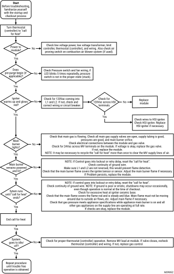
Flame Current Measurement
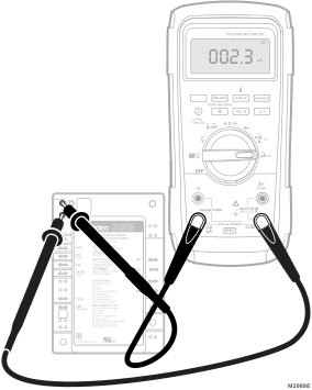
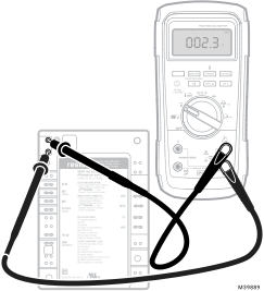
Flame current of the device can be measured using a standard micro-ammeter or voltmeter by simply putting the meter probes into the holes as shown in Measuring flame current with micro-ammeter. and Measuring flame current with voltmeter. drawings.
-
Flame current must be measured with main burner lit.
-
Set meter to DC μ Amp scale on micro-ammeter or volts DC on voltmeter.
-
If using a voltmeter, for every 1 μA of flame current, 1v will be displayed.
Note: Trying to measure the main burner flame current in series with the wiring will not be accurate.
Recommended Minimum Flame Current:
-
1V DC is equivalent to 1 μ Amp DC minimum.
-
Must read a steady 1 μ Amp DC or 1V DC minimum.